thermopile wiring diagram
This circuit can be built with two different metals and they are coupled together by generating two junctions. Nest E Custom Wiring Diagram.

Milivolt Systems W Modern Thermostats Hvac School
The thermocouple diagram is shown in the below picture.
. View the interactive Imperial IFS-40 parts diagram at Parts Town to find the exact part you need and add to your cart right from the parts breakdown. Analog Digital Thermopile Application Note - TE Connectivity. Thermopile Wiring Diagram -.
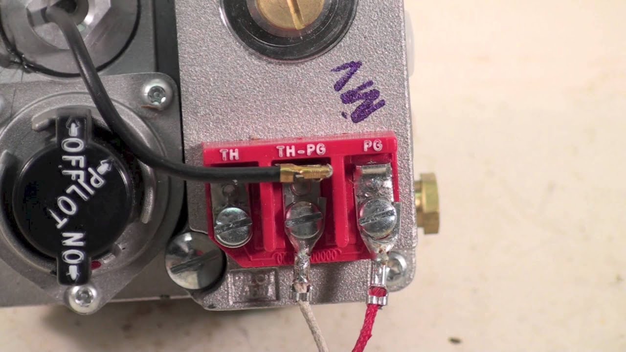
324K subscribers This is How to Wire the Thermopile to The 750mv Gas Valve for the Pilot and Main Gas Burners. The end of the thermopile wire branches off into two leads usually in red white colors. They operated like electrical conductors producing electrical.
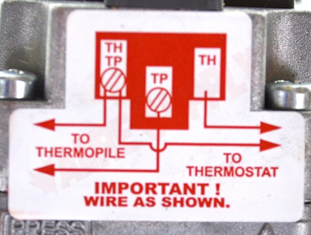
In this example were wiring a. The leads of the thermopile will be attached to the main valve. The thermopile should test out between 650 to 850 millivolts if it.
This includes a WIRING DIAGRAM. 1 Thermocouple connected directly to PLC. Hardy wood furnace wiring diagram.
Jan 3 2019 at 1101 PM at 1101 PM. With the largest in-stock parts inventory. 3 Humbucker 5-Way 2 Push Pull Wiring Diagram - Database -.
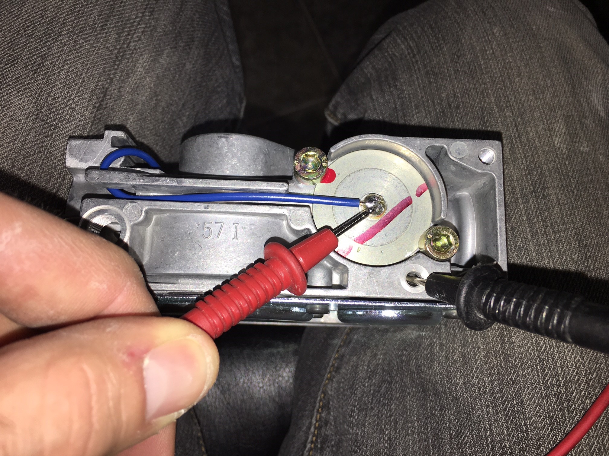
Official Post from AC SERVICE TECH. We can test the voltage. Thermopile ferromagnetic fept ordered nernst anomalous hysteresis.
Heater water thermostat electric wire 120v simultaneous wiring dual elements smart thermodisc wiring diagram. I show you how to Light the. A thermocouple fundamentally is an electrical device containing two wires created of various metals joined together.
Here are some basic wiring diagrams from the reference section of the Lesman catalog with rules to follow and some suggestions on specifying the right thermocouple wire. Lets look at an application where the thermocouple is connected directly to one of the module inputs. Ill show you how to test a thermopile on a water heater that has a Honeywell gas valve.
8 to 30 mv set meter to mv or volts dc place one lead to wire supplied place one lead to outer casing if the millivolt reading is less then 7 mv then change the thermocouple shutdown time.

Pitco Frialator 6ch1421 Natural Gas Pilot Orifice Thermopile Assembly Used Ebay

How To Test Your Thermopile Www Mygasfireplacerepair Com

Willy Widget Issue 4

How The Millivolt Gas Valve And 750mv Thermopile Work Troubleshooting Youtube

Proflame 584 Upgrade Kit

Mensi Propane Outdoor Gas Patio Heater Repair Replacement Parts Thermocoupler Dump Switch Control Safety Kit Amazon Ca Patio Lawn Garden
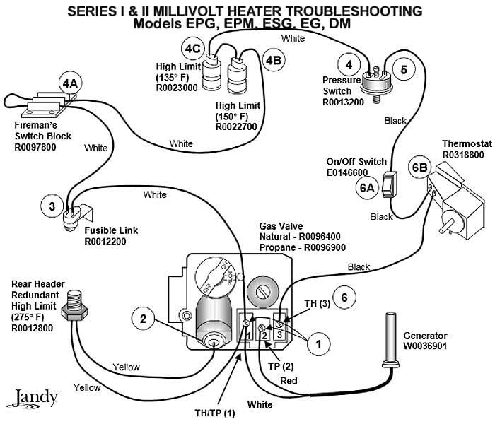
Millivolt Pool Heater Troubleshooting Guide Intheswim Pool Blog
How To Test Your Main Control Valve Www Mygasfireplacerepair Com

Pitco Millivolt Troubleshooting Youtube
710 502 Robertshaw Millivolt Dual Gas Valve 1 2 X 1 2 Low Profile Amre Supply

The Main Burner Flame Will Not Come On Or Stay On Www Mygasfireplacerepair Com

How The Fireplace Thermopile System Is Wired Youtube

750 Millivolt Gas Valve Thermopile Wiring Wiring Diagram Youtube

Controlling An Ancient Millivolt Heater With A Nest By Chris Vale Medium

Electrical How To Find The Right Thermostat For My Gas Fireplace Home Improvement Stack Exchange
52 Communication With With Possible Srs Only

Installing A Eve Smart Switch To Control My Gas Fireplace To Find Out The Power Is Provided From The Pilot Light In Millivolts From The Thermopile I Would Like To Turn On Off